
")


.svg) Steven Dam
Steven Dam
Rethinking Requirements Derivation: Part 2
By John Fitch, for Project Performance International (PPI) [Fitch, John. “Rethinking Requirements Derivation: Part 2.” PPI Systems Engineering...

Most of the community thinks the term “Agile” refers to Agile software development and the “Agile Manifesto.” The Agile Manifesto (Figure 1) is the driving statement behind the Agile Software Development movement. When you hear about “Agile,” it’s usually in terms of Sprints, Epics, and SCRUMs (processes), and tools like Kanban Boards implemented in popular software tools, such as Jira, GitHub, GitLab, etc. This almost seems like a contradiction to the “individuals and interactions over processes and tools.”
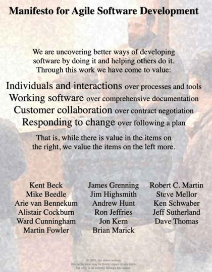
Figure 1. Agile Manifesto
All these processes require “functional requirements” to begin. So, what’s the source of these requirements? Model-Based Systems Engineering
Model-Based Systems Engineering is all about requirements. Engineers derive requirements from user needs, constraints (laws, standards, policies, etc.), and functional analysis of business processes (mission analysis or mission engineering). Systems engineers support the acquisition process by creating “specifications,” or requirements passed down to a lower level of decomposition. SEs also support the Verification and Validation (V&V) process by creating V&V requirements and making sure that the V&V results demonstrate that those requirements were met and through traceability to the original requirements that the customer needs are also met.

Figure 2 below shows a popular lifecycle model, the “V” Diagram. The “V” shows the different stages of development for a system or system of systems since each level down if often treated as its own system. For example, an Airline’s overall operating system consists of airplanes that consist of engines, each of which is often dealt with as its own system. In fact, the “V” Diagram is often used again for each of the components of the system. That hierarchical decomposition enables us to break down the user needs into small enough pieces that can be built or bought. One of the risks in this process is loss of traceability. If we can’t trace a requirement for the engine back to the original Airline’s operational need, then it’s difficult to know if that need is met. Another risk is that systems often become more than the sum of their parts. This is called emergent behavior. In-depth (stochastic) modeling and simulation early in the design process enables the systems engineers to predict possible emergent behavior.
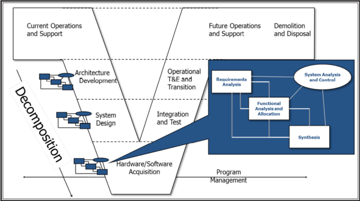
Figure 2. “V” Diagram
There is also a repeated systems analysis process going down the “V.” This process contains the classic systems engineering disciplines of requirements analysis (including the analysis of user needs and constraints), functional analysis (modeling of business processes to derive functional requirements), and allocation, which depend on the next step, Synthesis. Synthesis is the process of identifying the physical components of the next level of decomposition from the system level we identify subsystems, to the subsystems we identify components, all the way down. Allocation helps define the interfaces between the physical components. Good systems engineering practice means the interface should be as simple as possible and adhere to standards to make the system more modular and open to technology enhancements. This best practice has its own name: the Modular Open Systems Approach (MOSA). The last item in that chart is the “Systems Analysis and Control,” which includes the “programmatic” activities, such as risk analysis and configuration management, as well as simulation of the modeling. Some systems engineers include all of V&V in systems analysis and control, but there is a separate process for that.
Many people read this systems analysis process as a “waterfall,” in other words they assume you do requirements analysis first, functional analysis second, and synthesis third. In fact, this was meant to be an iterative process as can be seen in the diagram below.
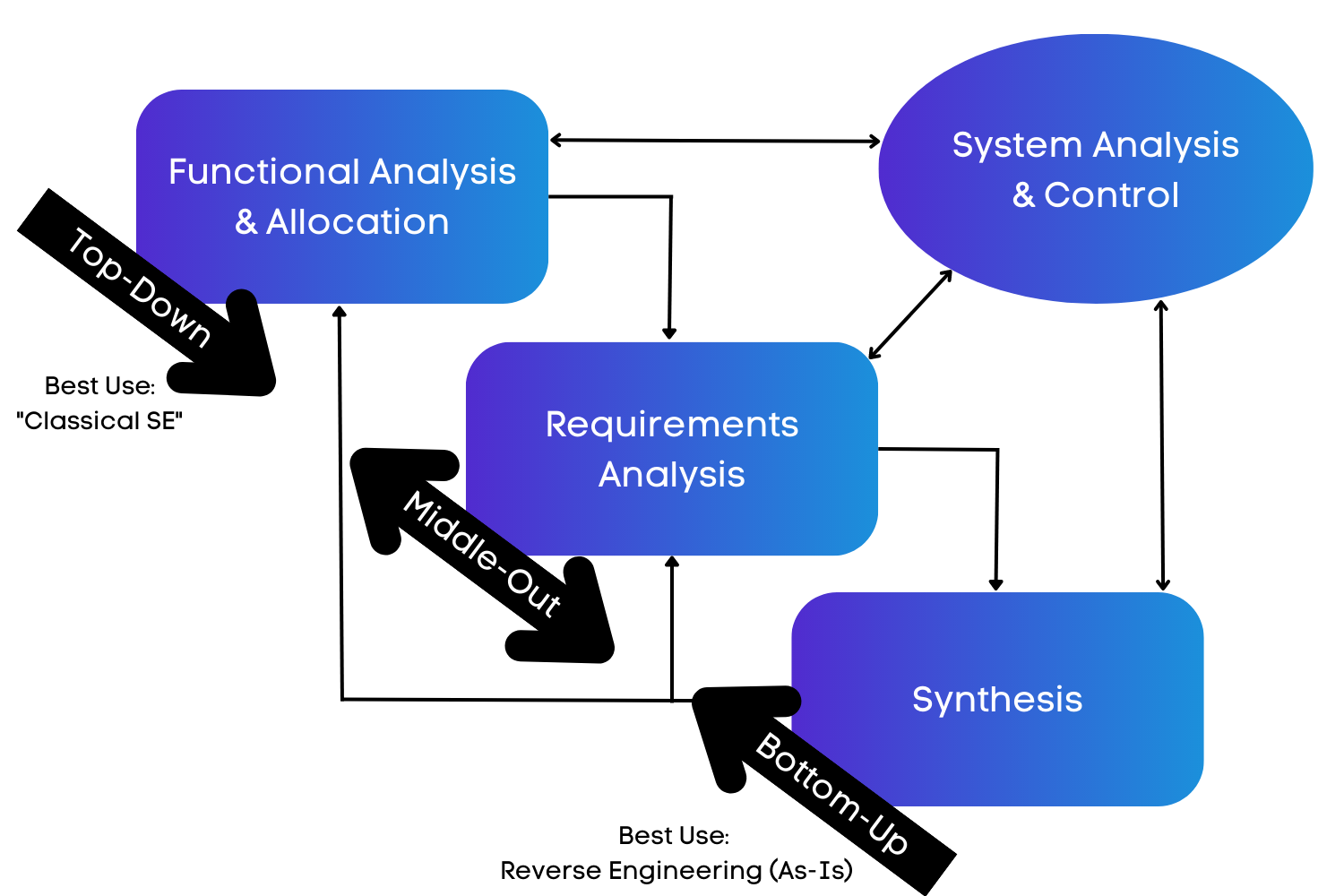
Figure 3. Diagram of Processes
The “top-down” or “waterfall” approach forms the basis for classical systems engineering. However, notice the two-way arrows on the chart indicating feedback loops. In fact, many of the formulations of this diagram don’t show a starting point. As a result, you could use this same process for reverse engineering, the basis for structured analysis’ 4-step process, and a practical way to address the “as-is” architecture.
However, what if your real goal is to develop a “to-be” or vision architecture? Often with “vision architecture,” you aren’t given a detailed set of requirements to start with. The customer’s requirements are very broad and unclear. For example, when I was asked to help develop the “Vision Architecture for Airborne Reconnaissance,” I was told to make it Joint Vision 2010 compatible. I went to this wonderful strategy document and found the one sentence on airborne reconnaissance. I had full traceability to my requirements at that point, but I needed more. Fortunately, I had been working on a number of Advanced Concept Technology Demonstrations (ACTD) before this and had formulated the middle-out approach to develop a system of systems.
The case with the move to “Agile” is essentially the same situation as these “vision architectures.” The customer’s needs are often nebulous and must be grounded in the current business processes (in the military these are called Tactic, Techniques, and Procedures). We can use functional analysis as the main starting point for the in-depth analysis needed. Agile Systems Engineering focuses on satisfying the customer through early and continuous delivery of valuable capabilities, planning for evolving requirements, and delivering working capabilities frequently.[1] We used to call this incremental development or “pre-planned product improvement (P3I).”
A detailed version of the Middle-Out Process can also be viewed in a timeline view. Figure 4 below shows the key steps in this process.
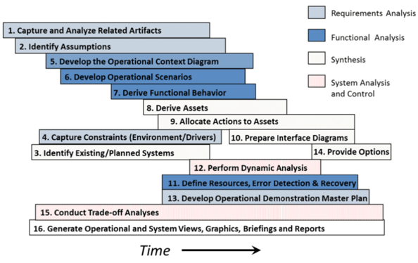
Figure 4. Timeline of Middle-Out Process
The steps are numbered to indicate their nominal start sequence. Notice that most of these steps overlap, which demonstrates the concurrent, iterative nature of this process, which is a key goal of Agile Systems Engineering. This process provides the necessary information for executing the resulting architecture, including the requirements analysis and operational demonstration.
Middle-Out Process Steps
Step 1: Capture and Analyze Related Documents. First, obtain any related documents, capture them in the system repository (e.g., Innoslate®), and analyze them to identify issues, risks, and assumptions for other activities and capabilities.
Step 2: Identify Assumptions. Identify the assumptions made in Step 1 and review those assumptions with the customer to ensure that subsequent steps in this process will meet project objectives. Capture these assumptions and decisions in your tool of choice and document them.
Step 3: Identify Existing and Planned Systems. I recommend conducting a survey of the current and ongoing activities related to this system, ensuring that capabilities already available or planned are taken into account in this system. This step reduces unnecessary duplication of effort. Coordination and monitoring of the progress of related planned systems (or other components) must also be included in this step. Planned “systems” that are interfaced with or incorporated as part of the system should be used to enhance transition planning.
Step 4: Capture Constraints. In this step, capture the technical, schedule, and political constraints imposed by external laws, policies, regulations, and standards. These constraints often come from the previous three steps, as well as later analyses.
Step 5: Develop the Operational Context Diagram. The operational context diagram is an extension of the classical context diagram used in systems engineering, extended to include interactions between external systems. It describes the overall architecture environment, including interactions between stakeholders, external systems/architectures, facilities, and resources.
Step 6: Develop Operational Scenarios. In this step, you will develop a set of operational scenarios that represent the scope of potential uses of the “As-Is” system. Some call these “use cases” or “threads.” We have found that building a set of scenarios from the simplest case to the most complex and reusing activities/functions provides an effective way to create a concept of operations (CONOPS). These scenarios represent typical user and system processes. These scenarios can also form the basis for the test scenarios in the Operational Demonstration Master Plan (ODMP) or Test and Evaluation Master Plan (TEMP).
Step 7: Derive Functional Behavior. In this step, you will derive the overall functional behavior from the individual scenarios developed as part of Step 6. Select a scenario set that builds upon each other instead of coming up with a dissimilar, overlapping set. The results of this step provide the final functional behavior model.
Step 8: Derive System Elements. In this step, you will derive the system elements from the functional behavior (packaging the functionality) and the potential COTS, GOTS, and legacy systems. You will create components that provide the simplest interfaces between system elements.
Step 9: Allocate Functions to System Elements. This step goes hand-in-hand with Steps 7 and 8. During this step, you will allocate functions to system elements to establish the traceability between functional behavior and the system elements. You can also use this step to distinguish between operational activities and system functions.
Step 10: Prepare Interface Diagrams. This step continues the allocation process, ensuring that you have documented what data elements flow through which interfaces. Most of this becomes obvious when you complete Step 9, during which the functional allocation to system elements defines the data that must flow between the elements. However, after Step 9, you need to determine the mechanism for the data transmissions and create the resulting diagrams.
Step 11: Define Resources, Error Detection, and Recovery Processes. As part of the scenario development and functional behavior analysis, you need to include the effects of non-ideal processes, where errors and other alternatives are detected and corrected as part of the process. This step enables you to build in command and control, as well as security (cyber and physical) processes. In addition, the use of any resources will be included in the functional analysis developed under Steps 6 & 7.
Step 12: Perform Dynamic Analyses. Just like in Step 11, you need to perform dynamic analyses of the individual scenarios, the overall functional behavior, and the overall behavior as constrained by the physical architecture, including the interface capacities and latencies. Clearly, this step must be performed concurrently with Steps 6, 7, and 9 to develop an executable system architecture.
Step 13: Develop Operational Demonstration Master Plan. It is critical that you create a draft of the Operational Demonstration Master Plan (ODMP) or Test and Evaluation Master Plan (TEMP), as part of the architecture development process. The document’s purpose is to enable the future acceptance testing of the resulting system design and to demonstrate potential issues and problems that will require resolution in the system. You should include people who know test and evaluation processes and capabilities as part of your team in developing this document. This step shortens the V&V time significantly.
Step 14: Provide Options. It’s important to realize that creating a system is not a useless activity. During the process, you will identify any potential problems, shortfalls, or gaps with the “As-Is” architecture and provide options to resolve these problems. Plan to create a briefing that summarizes these options, even if the options have been decided during the process, and incorporate them in the documentation. Note also that you should have the information necessary to create/update the project plans for the detailed development, acquisition, integration, and verification phases of the project.
Step 15: Conduct Trade-off Analyses. All through this process, you will perform trade-off analyses using stakeholder-validated evaluation criteria to derive requirements, select scenarios, and select components, including COTS, GOTS, and other potential options. Summarize these as part of the options (Step 14) at the end of the process and present them to the customer.
Step 16: Generate Views, Briefings, and Reports. This last step recognizes that throughout any system project, you will have to produce reports and briefings to show status and progress. By using the technique and tools selected (particularly Innoslate®), we have found that the development of reports and briefings is now a simple by-product of the process. Midway through this process, you have sufficient information to develop a solid concept of operations (CONOPS). We have found developing one early and updating it as the design matures can provide great communication between you and the customers/users.
You can repeat this process in layers for each level of decomposition, assuming roughly 3 to 4 levels per major “V” area (architecture, system design, and acquisition). By taking this approach, you can create many system deliveries based on a complete pass through the process. If applied correctly, you can converge on a solution.
The main features of this Agile systems engineering approach are that it is iterative, event-driven, consists of parallel tasks, provides products as needed, and can implement model-based reviews. This approach relies on using a modern, collaborative tool such as Innoslate to organize and track the information gathered by a team of systems engineers. Get started using an Agile approach to Systems Engineering today and see what it can do for your system and team.
Learn how Agile methodologies can help you win federal contracts!


By John Fitch, for Project Performance International (PPI) [Fitch, John. “Rethinking Requirements Derivation: Part 2.” PPI Systems Engineering...
By John Fitch, for Project Performance International (PPI) [Fitch, John. “Rethinking Requirements Derivation: Part 1.” PPI Systems Engineering...
This blog is in response to a Reddit post by Rhedogian, “Change My View: Model-Based Systems Engineering in 2024 is at best overhyped, or is at worst...