
")


.svg) Steven Dam
Steven Dam
Rethinking Requirements Derivation: Part 2
By John Fitch, for Project Performance International (PPI) [Fitch, John. “Rethinking Requirements Derivation: Part 2.” PPI Systems Engineering...

The saying, “A picture is worth a thousand words,” means pictures are an efficient tool to convey information. In systems engineering, a Data Management Plan (DMP) works the same way. It organizes a complex data set, allowing anyone to understand it immediately.
The immediacy of a well-crafted DMP can take your system engineering projects to the next level. Built on the foundation of Lifecycle Modeling Language (LML), it makes complex systems easier to digest, even for the least technical stakeholder. This shows how powerful a tool it is for tackling the complexity of today.
This guide summarizes the best practices for creating DMPs. The goal is twofold: we want to help new Innoslate users start creating DMPs while also helping long-time users improve theirs.
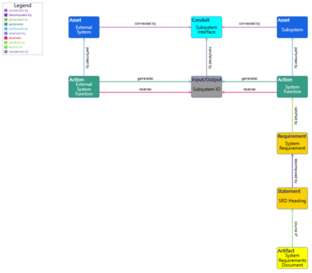
Figure 1: Example of a Logical Data Model (LDM), a part of the DMP
SUMMARY OF BEST PRACTICES
Step 1: Identify the Scope
The first step is identifying the scope of the data you are trying to capture in your DMP. This stage is vital because knowing the scope of a project helps you capture all the data elements. For example, is the model strictly at the system level or does it also include the subsystem level? If it includes both, you may need to account for multiple functional models. The level of detail in the data usually drives this. Step #1 will give you a general idea of what your DMP will look like, how to structure it best, and more information to get your DMP started.
Step 2: Break Down the Data
The second step is breaking down the data into its logical data elements. In other words, you need to identify what data you need to represent in your DMP. Some examples of logical data elements are systems, subsystems, system/subsystem functions, system/subsystem requirements, and connections. If the system is a car and the subsystem is an engine, then a system function is, “Provide Transportation Between Locations,” and a subsystem function is “Provide Power.” Figuring out your logical data elements is indispensable.
Step 3: Identify Classes
The third step is where you begin constructing your DMP. After identifying the applicable data elements, map them into LML classes. For example, asset entities can represent systems and subsystems, action entities can represent system/subsystem functions, requirement entities can represent system/subsystem requirements, etc. You also need to determine the relationships between these data elements.
The most recent LML Specification contains a list of classes and relationships that you can use as a reference. Do not add additional relationships to the schema if they will cross project boundaries (see Step #4). Only extend classes with additional attributes when there is no other option. Moreover, consult the Innoslate Representation Standards for suggestions on color-coding your data elements by class.
Step 4: Identify Project Boundaries
The fourth step is identifying where the project boundaries should exist. Once you have laid out the data elements and significant relationships, you should determine the project boundaries based on what information you want/need to restrict access to (e.g., financial information, subcontractor design details). Hierarchies in the data and types of information stored tend to drive project boundaries.
Step 5: Create a Numbering Scheme
The final step is creating a numbering scheme for your DMP. This makes it easier to find data when sorting by number. One suggestion that makes for an effective numbering scheme is to use a mnemonic or an acronym at the beginning of your number so that you can quickly remember what the DMP represents. For example, if you’re creating a DMP for a Verification Requirements document, use the numbering scheme of VR.1, VR.2, etc.
Innoslate has an auto-numbering tool that makes creating a numbering scheme easier. However, keep in mind that the auto-numbering tool renumbers everything in a diagram. Also, if you add a prefix in the auto-numbering tool, also add a period after it, e.g., put “VR.” instead of “VR” in the tool. If you account for these cautions, auto-numbering is an efficient way to implement your numbering scheme into a DMP.
Creating a DMP tends to be an art, not a science. There are no hard-and-fast rules on how to do it. Nevertheless, these five steps can set you on the right path to mastering the art.
Ready to streamline your systems engineering process? Try Innoslate today and experience the power of efficient collaboration and documentation. Sign up for a free, sandbox account now!

By John Fitch, for Project Performance International (PPI) [Fitch, John. “Rethinking Requirements Derivation: Part 2.” PPI Systems Engineering...
By John Fitch, for Project Performance International (PPI) [Fitch, John. “Rethinking Requirements Derivation: Part 1.” PPI Systems Engineering...

This blog is in response to a Reddit post by Rhedogian, “Change My View: Model-Based Systems Engineering in 2024 is at best overhyped, or is at worst...